|
Main Menu
|
|
|
|
My 2007 4Runner
|
|
|
|
4Runner History
|
|
|
|
Other
|
|
|
|
|
Concept:
If you have been following the build up of my Toyota 4Runner, you know by now that
I special ordered it
and chose to include the optional Toyota Factory Navigation System. This was a $2,137 invoice ($2,620 retail) option which included a JBL® AM/FM 4-disc CD changer,
voice-activated DVD navigation system, satellite radio capability, hands-free phone capability via Bluetooth® wireless technology, backup camera,
eight speakers and MP3/WMA playback capability.
When special ordering I also chose NOT to get the factory rear seat entertainment system (RSE). I preferred instead to install my own
in car entertainment system (ICE) as the system I went with
offered much more functionality for a similar price as the OEM option.
One thing I gave up by going with an aftermarket video system was the ability to play DVD's on the factory navigation screen.
Toyota's system does allow this, albeit while in park only.
This modification will add the ability to play DVD's on the factory navigation screen and take it a step further.
It will allow for video playback on the factory nav screen from your choice of two different video sources, both while parked and while in motion
(for your passengers enjoyment only). Additionally, this mod will allow you to activate the factory backup camera anytime, rather than in reverse only.
What needs to be accomplished:
The factory Toyota navigation setup has a backup camera system that when the vehicle is put into reverse, it automatically sends a video signal from the backup camera housed within the
rear tailgate, up to the nav screen.
First, we will add a switch to fool the nav system into thinking the vehicle is in reverse even though we are not. This "anytime backup camera" switch will activate the camera and
automatically force the nav screen to change from whatever is currently being displayed on it (such as maps, audio, etc.), to a direct video feed from the camera.
At this point, using a secondary three position switch, we will hijack the backup camera signal and replace it with our own video signal,
in this case either one of my dual independent dvd headrest players. Audio can be heard thru the FM modulator feature of the Vizualogic DVD players which
wirelessly outputs the user selected audio source information via one of seven user selectable FM frequencies to the vehicle radio.
Building the navigation video and anytime backup camera module:
So we need to build an electronic switching circuit that will allow the user to switch what is shown on the navigation screen at anytime between
backup camera, DVD player A and DVD player B. Two switches and a series of relays will accomplish this.
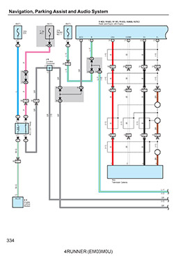
Here is the navigation video and anytime backup camera mod, in schematic form that I created which also shows how it is wired into the factory Toyota 4Runner navigation system.

J.A.'s Navigation Video and Anytime Backup Camera Module Schematic |
Here are some of the parts needed to build the Navigation Video and Anytime Backup Camera Module.
I designed it around a nice small project box to make it able to discretely be located under the passenger seat next to my Vizualogic A/V control unit.
Some parts that I included are;
Project Enclosure with mounting bosses and flush textured cover. 4.165" x 2.800" x 1.000". Polycase LP-31P
Perforated PC Board 3-3/16" x 2-1/2". Parts Express #320-460
(2) Gold plated yellow terminal RCA Video Jacks. Radio Shack #278-2075
(7) 2-Position PC Board Screw Terminals Block Connectors, 5mm Pitch 'B'. These make for easy on vehicle installation rather than direct soldered main connection wires
(4) Panasonic DS2E-S-DC12V DPDT 12V PCB Mount Relays
(2) 1N4001 50V 1A 1000mA DO-41 Rectifier Diodes
(2) 1ft RCA Digital 75ohm copper braid shielded coax video cables with gold terminals and fully molded connecters, UL listed
22 Awg Plenum jacket 2 conductor wire with Foil Shield. UL listed & CL3 rated.
22 Awg Plenum jacket 4 conductor wire with Foil Shield. UL listed & CL3 rated.
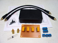
Parts |
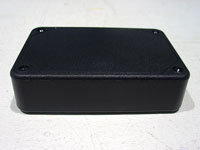
Polycase LP-31P |
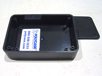
Inside of project box |
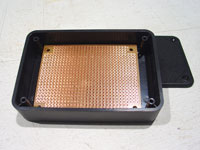
Test fit pc board |
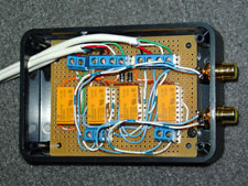
The completed navgation video and anytime backup camera module and what it looks like fitted into the project box.
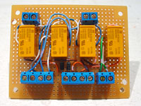
Completed Nav Video Module
Front |
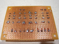
Completed Nav Video Module
Back |
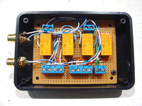
PCB mounted to Project Box |
Before installation, I tested all the completed circuits for continuity using a digital multimeter ensuring I would have no problems during installation on the vehicle.
Installing the navgation video and anytime backup camera module:
Begin by remove navigation unit to access the wiring behind it.
Remove driver side lower finish panel.
Start out by disassembling the lower dash area.
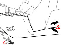
First remove the two 10mm bolts holding the lower finish panel on. Pull the panel straight out to disengage 4 plastic clips still holding it on.
The trim ring around the key hole will just pop out on it's own as you are doing this. Remove the wire harnesses attached to each of the switches
located on the back side of this panel. Also on the back right side of this lower finish panel is the room temperature sensor harness (cooler thermistor),
detach this from the panel as well. You may leave the fuel door release and the hood release handles attached to the panel. The panel can be lowered
to the floor now.
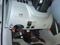
Remove driver side
lower finish panel |
Pull to release 4 clips |
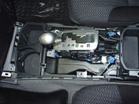
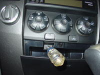
Center Console Removal.
To remove the center console, start by removing the shifter cover. It is held on with five clips and two claws. To remove you simply pull straight
up and back towards the rear of the vehicle. Before you can set the shift cover aside you need to remove any wire harnesses attached to it.
In my case I had to remove the DAC switch wiring and the 12v power point wiring. You may have more if you have the seat heaters,
rear air suspension or cigarette lighter options.
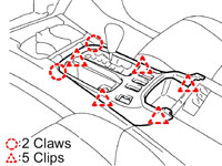
To remove shift cover
Pull to release 5 clips |
Next the console cover gets removed, this time there are 6 clips and two claws. To remove, again, pull straight up and back towards the rear of the
vehicle.
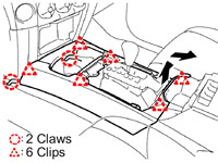
To remove console cover
Pull to release 6 clips |
Before you can lift out the center console itself, you need to remove the upper panel side garnish. To remove, unclip the side covers just in front of
and below the cupholders. Then slide rearward to remove.
To remove side garnish
Pull to release 1 clip |
Then using a 10mm socket, remove the six bolts holding the console in place.
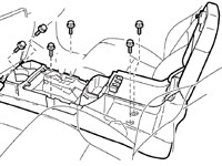
Remove six 10mm bolts |
Bolts removed |
Disconnect 4 more harnesses (automatic transmission shift lever illumination, accessory input for stereo, 115v power point and cup holder illumination),
then lift out entire console and set aside.
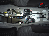
Lift out center console |
Set console aside |
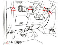
Center Instrument Cluster Removal.
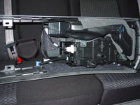
To remove the center instrument cluster, start out by opening the storage bin under the climate control assembly.
Using a 10mm socket, remove the one bolt that is in there.
Using a 10mm socket |
Remove bolt |
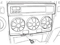
Disengage the 4 clips and remove the air conditioner assembly, and then disconnect the wiring connector on the back.
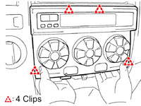
Pull to release 4 clips |
Pull forward and disconnect wire harness |
Climate control assembly removed |
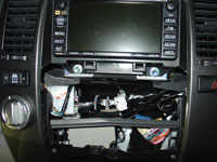
Now you can remove the center instrument cluster finish panel sub-assembly. First remove 3 bolts using a 10mm socket.
Then disengage the 8 clips. At this point you can disconnect the three wire connectors from the hazard lights, rear window control and 4WD selector.
Set the panel aside.
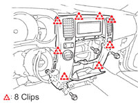
Remove 3 bolts
Pull to release 8 clips |
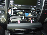
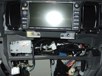
Using the 10mm socket, this time with and extension bar, remove 4 bolts holding in the navigation unit. Pull the navigation unit straight out. In order to work on the wiring, you will
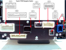
need to disconnect the 9 wire harnesses on the back side. Then set the navigation unit aside.
Center instrument cluster finish panel removed |
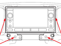
Remove 4 bolts
Pull navigation unit straight out |
Remove 4 bolts
Navigation connectors |
Wire Connections:
With the navigation unit out of the dashboard, it is time to splice our module into the factory wiring.
I have already decided that I am going to mount the homemade navigation video and anytime backup camera module under the passenger seat next to my Vizualogic A/V control unit.
The purpose for this location is so that I can keep the RCA cables that are needed to get the source video from the A/V controller as short as possible.
I started out by running my wiring first. The most important wires for this modification are those that will carry the video signals from the project box to the navigation screen.
These wires need to be shielded, just like the factory backup camera wiring is. I purchased 22 gauge plenum jacket 4 conductor foil shielded wiring bundle for this run.
Since I also needed a 4 wire bundle to go from the project box to the switch panel, I purchased additional footage of this same shielded wire for simplicity even though
the switch wires do not require shielding. While at it, I also ordered the same wire in 2 conductor form to be used for the reverse camera trigger wire run.
I routed in the cabling starting at the project box located under the passenger seat, then under the carpeting over to the center console, along the center console and up into the dashboard.
When the three cable bundles were in place, I began to make the splice connections.
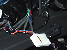
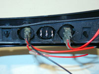
First I connected the 2 wire cable to the backup camera trigger wire. The backup camera trigger wire is the red wire with yellow stripe located at pin5 in the R9 connector.
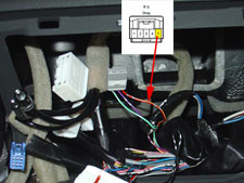
Backup camera trigger wire identified |
Splice made at reverse cam trigger wire
ready to heat shrink |
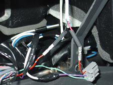
Then I connected one of the 4 wire cables to the backup camera video wires. The positive backup video wire is the solid black wire located at pin22 in the R26 connector.
The negative backup video wire is the solid gray wire located at pin23 in the R26 connector. The factory electrical wiring diagram lists this negative backup video wire
as solid brown but for some reason mine was solid gray.

Backup camera video wires identified |
Splices completed at the
backup camera video feed wires |
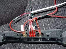
At this point, and before working on the 4 wire switch cable, I made all the wire terminations inside the nav video module, put the cover on the box and connected it via 1' RCA cables to the
A/V control box. Refer to the schematic for wire connection points.
10 wire connection |
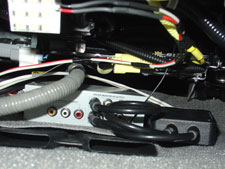
nav video module location |
Install Switches:
Two switches are needed for this mod.
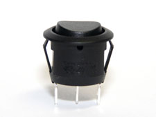
The first will be for activating the backup camera "anytime", ie. even while driving forward. I will use a round rocker switch with amber led that matches the one I used for my
Navigation Override and Unlock Bypass Mod.
The second will be used to choose between backup camera (center position), DVD player A (driver side headrest player, switch put to the left position)
and DVD player B (passenger side headrest player, switch put to the right position) .
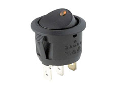
Round rocker switch
with amber led |
Three position switch
on-off-on |
12V round rocker
switch info |
Switch information:
12V Round Rocker with Amber LED. Oznium.
Switch Type: Rocker Switch
Circuitry: Single Pole Single Throw (SPST)
Terminals: 3 standard male brass blades, 0.25" wide x 0.295" long (6.35mm x 7.5mm).
Up Position: On (2-1).
Down Position: Off.
Electrical Rating: 10 amps at 250V AC, 15 amps at 125V AC
Illuminated: Yes.
Housing: Black plastic bezel and actuator.
Mounting Panel snap-in.
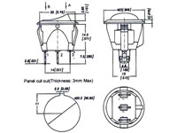
Panel Thickness: fits panels 3mm max thickness.
Mounting Hole Dim. Inch 0.775" (19.8mm).
Bezel Size: 0.906" (23.0mm).
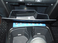
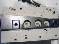
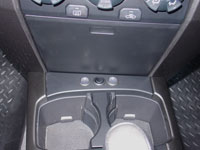
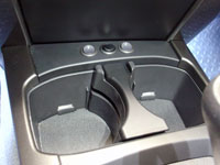
I decided to locate the switches that activate this mod on the blank panel right behind the cupholders. I found a nice 12V round rocker switch with amber led that only required
a simple 3/4" hole to be drilled for installation. This switch fits perfect and is low profile enough that it allows the bin under the radio to open fully without interfering
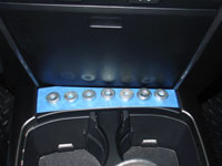
with the switch. I used 3/4" washers to layout the spacing and check for clearance before drilling.
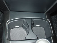
4Runner center console
cupholder area |
Laying out switch panel |
Checking for clearance |
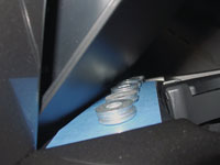
Checking for clearance |
You will notice I'm installing three of these switches in total. The third is for my Navigation Override and Unlock Bypass Mod.
This panel will hold between five to seven switches depending upon the spacing used between them.
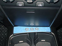
Drawing the drilling pattern |
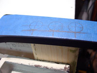
Preparing to drill |
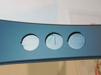
Holes for switches drilled
switch notches carved |
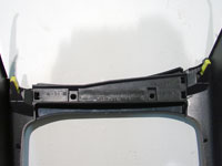
Underside of center console |
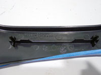
Panel support |
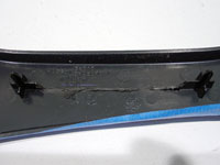
Panel support removed |
Support panel drilled |
Switches mounted |
Switch panel wired up |
Round rocker switches |
Switches installed |
After completing the installation of the navigation video module, associated wiring and switches, reinstall the navigation system back into dash.
Results:
While this will not be one of my most frequently used mods, it is a really cool feature to have and it was a rewarding experience researching, planning, building and sucessfully executing the mod.
The Anytime Reverse Camera feature can be quite useful while towing and wanting to check on the hitch connection.
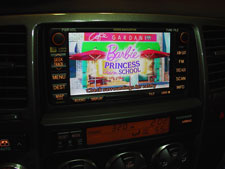
The Video on Nav mod will be a nice feature for the passenger on long trips. It will also come in handy to see what the rear passengers are looking at while encountering their questions
on the usage of the DVD players.
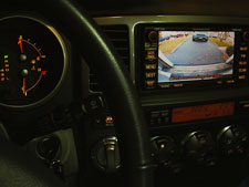
Anytime reverse camera
shown while in park |
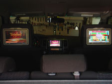
Video on Nav
switch set to DVD player 'A' |
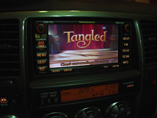
Video on Nav |
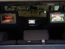
Video on Nav
switch set to DVD player 'B' |
Video on Nav |
|
|