|
Main Menu
|
|
|
|
My 2007 4Runner
|
|
|
|
4Runner History
|
|
|
|
Other
|
|
|
|
|
Concept:
This modification will change the operation of the factory maplights (personal lights) on the 4th generation Toyota 4Runner
so that they automatically turn on when any door is either unlocked by a key or keyless transmitter, or if any door is opened.
The standard feature that shuts the maplights off 30 minutes after they have been left on after the ignition is turned off will be retained to prevent
battery drain.
Additionally a switch will be added so that this mod can be turned off if so desired. A switch will come in handy when working on the vehicle
for long periods of time while repeatedly opening and closing the door, which will reset the 30 minute automatic dome relay power off feature.
What needs to be accomplished:
This mod requires that the Body ECU's ILE (Interior Light Enable) circuit be brought to an unused terminal on each of the two factory maplights.
There are a few locations where the ILE circuit can be tapped into. You need to tap into only one.
1) Interior Dome Light, pin #2, solid white wire. For those without a sunroof, you can tap into ILE here and snake the wire forward to the maplight.
Since I want a dash mounted switch to be able to turn the maplight mod off as desired, it defeats the purpose of using this convenient tap in point.
2) 'A' Pillar roof wire bundle. If you have a sunroof and don't want to add a dash mounted switch, you can make the ILE tap in here and not go through
the process of opening the lower and upper portions of the dashboard.
3) Driver side interior relay/junction box. Front side, Roof wire harness connector 1A, Pin #8, solid white wire
(note: there is more than one solid white wire within this connector).
4) Driver side interior relay/junction box. Back side, Instrument panel wire harness connector 1K, Pin #9, red with green stripe wire.
To maintain a factory appearance, make your tap into the ILE circuit back here and it will be less visible.
I choose to tap into the ILE circuit using method #4.
Procedure:
Remove driver side lower finish panel for access to driver side interior relay/junction box.
Start out by disassembling the lower dash area as we need access to the driver side interior relay/junction box. To access this area,
first remove the two 10mm bolts holding the lower finish panel on. Pull the panel straight out to disengage 4 plastic clips still holding it on.
The trim ring around the key hole will just pop out on it's own as you are doing this. Remove the wire harnesses attached to each of the switches
located on the back side of this panel. Also on the back right side of this lower finish panel is the room temperature sensor harness (cooler thermistor),
detach this from the panel as well. You may leave the fuel door release and the hood release handles attached to the panel. The panel can be lowered
to the floor now.
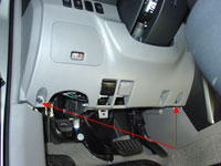
Remove driver side
lower finish panel |
Pull to release 4 clips |
Remove lower bracket:
Remove two 10mm bolts holding the metal bracket around the bottom of the steering column. Disengage the 2 claws and remove the instrument panel lower
left hand bracket. Set bracket aside.
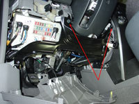
Remove instrument panel
lower bracket |
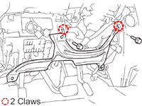
Disengage 2 claws |
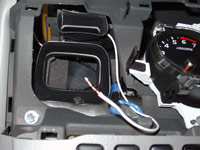
Lower down the driver side interior relay/junction box:
Remove wire clip and wire connector under steering column.
Remove three bolts holding driver side interior relay/junction box in place.
Remove bolt & bracket.
Pull down driver side interior relay/junction box to access back side.
Remove wire clip
and wire connector under steering column |
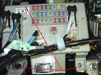
Remove three bolts |
Remove bolt & bracket |
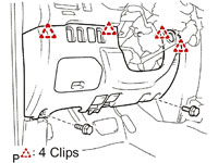
Remove instrument cluster finish panel.
Pull firmly straight out to release seven clips.
Remove Rheostat (dash light dimmer) by unclipping wire harness on the back, depressing two tabs on this switch (top and bottom) and pulling the switch
out the front of this panel. Set panel aside.
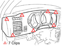
Remove instrument cluster
finish panel
Pull to release 7 clips |
Remove front driver side 'A' Pillar trim.
Using a screwdriver with the tip wrapped in tape to avoid scratches, remove the 2 assist grip plugs. Remove the 2 10mm bolts. Using a screwdriver,
disengage the claw. Pull to release two clips. Set pillar garnish aside.
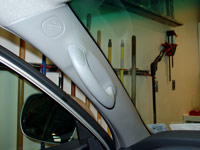
Remove front 'A' pillar trim |
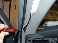
Disengage claw |
pull to release 2 clips |
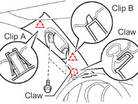
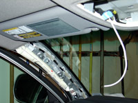
Remove roof console box assembly.
Open the sunglass holder and grasp the interior of the box while using a screwdriver to pull down on the windshield side of the box. You will need to pull
down very firmly to release the two clips here. Once the clips release, pull the box towards the windshield to disengage the 3 claws.
Disconnect the map light switch connector, the navigation microphone connector (if so equipped) and moon roof switch connector (if so equipped),
remove the console box and set aside.
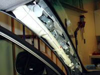
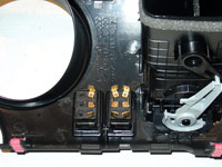
Wire the maplight switches.
Use a small screwdriver to pry off the two factory maplight switches. You will notice there are two prongs coming out of the console but three holes
in the switch. Strip approx. 1/2" of the insulation off a section of 18 gauge wire and insert it into the unused switch input on each of the switches.
Run these two sections of wire over to the left side of the roof console box. Splice them together. I used a blue 3M Nylon Fully Insulated Female
Disconnect with insulation grip interlock barrel. Blue is typically for 16-14awg wire but works well when two 18awg are twisted together such as in this
case.
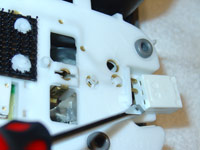
pry switches off |
add wire to unused input |
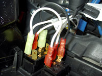
Bench testing.
Good time for a test before going any further. Open the hood of the vehicle and clip on a pair of test leads to the battery. Bring the ground wire to
the wire you just added to the switches. With the maplight switches off, bring the positive (12V+) lead to pin #5 of the map light switch connector.
The maplights should turn on (without depressing the switches).
bench testing |
Run wire to dash.
Using 18awg (American wire gauge) wire, and starting at the roof console area, snake the wire above the headliner and forward to the windshield.
Pull it out of the headliner and across to the 'A' pillar. Leave it hanging out of the headliner for now. Run it down the 'A' pillar following the
factory roof wire harness. Get the wire into the area where we will mount our switch. Now that we have the correct length for this wire, cut it from
the spool and now go back and tape it in a few places within the 'A' pillar as well as push the wire up into the headliner where it runs from the
roof console to the pillar.
Run wire above headliner |
Down 'A' pillar |
To dash mounted switch |
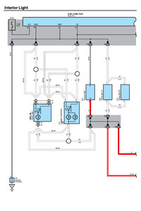
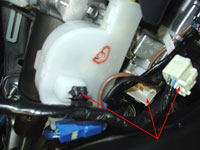
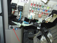
Tap into the factory ILE (Interior Light Enable) circuit.
As mentioned above, there are a few places to tap into the ILE circuit. I am going with the back of the driver side interior relay/junction box,
instrument panel wire harness connector 1K, Pin #9, red with green stripe wire. There are a couple of reasons for this. The ILE circuit wires available
on the front side (Roof wire harness connector 1A, Pin #8, solid white wire) and in the 'A' pillar (which comes from Roof wire harness connector 1A) are
ribbon wire type (multiple thin wires connected together in a ribbon) and are much harder to tap. Additionally making the tap on the back side is less
visible and maintains a more factory appearance.
I tapped into the ILE wire using a Red 3M Scotchlok 557 Electrical IDC (insulation displacement connection) connector which is perfect for 22-16 AWG solid
or stranded wire. The ILE wire appears to be, in my estimation, 20awg. Run your wire from here up to where you will mount the dash switch.
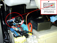
Connector 1K
Pin #9
Red with green stripe wire |
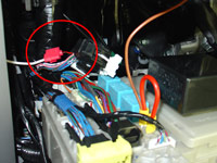
Scotchlok tap into ILE |
Switch information.
A switch is being added so that this mod can be turned off as needed. The switch will come in handy when working on the vehicle
with a door open for extended periods of time. While the vehicle does have an automatic dome relay power off feature, which cuts power to the
maplights (and dome lights) after 30 minutes of any door being left open, I still believe a switch will be useful.
While any 12V on-off switch will do, I chose to go with a SPDT (single pole double throw) switch with on-off-on functionality. The primary reason for
doing so was to match the look of the switch installed next to it, which is for my Footwell lighting mod. An added benefit of using a double throw switch
is that I can wire one of the 'throws' (the up position in this case) to be an instant on mode.
Cole Hersee Part# 58027-03
Switch Type: Rocker Switch
Circuitry: Single Pole Double Throw (SPDT)
Terminals: 3 standard male brass blades, 0.25" wide x 0.50" long (6.35mm x 12.70mm).
Up Position: On (2-1).
Center Position: Off.
Down Position: On (2-3).
Electrical Rating: 25 amps at 12 VDC.
Sealing: Weather resistant, gasket seal in housing.
Contacts: silver.
Illuminated: No.
Housing: Black plastic bezel and actuator.
Mounting Panel snap-in.
Panel Thickness: fits panels 0.093" to .187" (2.37mm x 4.76mm) thick.
Mounting Hole Dim. Inch 1.45" x .830" (36.83mm x 21.08mm).
Bezel Size: 0.964" x 1.69" (24.52mm x 43.16mm).
Actuator: inches 1.19" x .660" (30.3mm x 16.9mm).
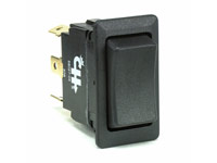
Cole Hersee SPDT 58027-03 |
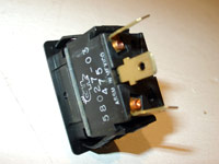
Cole Hersee SPDT 58027-03 |
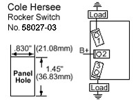
SPDT Switch Schematic |
Switch mounting.
The Cole Hersee 58027-03 switch that I chose to use fits perfectly in the instrument cluster finish panel (upper dash) cutouts with
no modification or trimming necessary to either the switch or the panel. Though the switch does not snap lock into place due to the
thickness of the panel, the fit on the sides is more than tight enough to hold it in place.
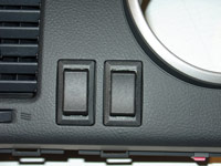
Switches mounted in dash |
A look from the back |
Switch wiring.
At this point we have already ran two wires to the switch location. The first was from the roof console and the second was from the ILE
circuit. I crimped onto the end of each of these two wires, a red 3M Nylon Fully Insulated Female Disconnect with insulation grip
interlock barrel. Red is typically used for 22-18awg wire. These disconnects fit quite tightly onto the switch prongs which is why I
prefer the type that have a insulation grip interlock barrel. These type of connectors require a double crimping method, the first to
secure the copper wire, the second on the wires insulation which further secures the wire. This helps to hold the wire securely in place
when you need to pull on the disconnect to remove it from the switch, which can be at times difficult to remove. A dab of dielectric
grease on the switch prong will help in any removal efforts as well.
Connect the roof console wire to the center prong on the switch.
Connect the ILE wire to the bottom prong on the switch.
Now for the third and final wire to go to the switch. This is only needed because I am using a double throw switch. Using a 5" piece of
18awg wire (the black wire in my pics), use a ring terminal on one end and a quick disconnect on the other. Screw the ring terminal end
to the screw that holds the driver side air vent to the dash reinforcement bar, this provides a constant ground source. Connect the other
end to the upper switch prong.
The switch is now wired to work as follows:
Up Position: Maplights turn on instantly (switch prongs 2-1 connected together).
Center Position: Maplight Mod Off.
Down Position: Maplights turn on (with fade feature) automatically when any door is either unlocked by a key or keyless transmitter, or if any door is opened (switch prongs 2-3 connected together).
Switches wired up |
Switches installed |
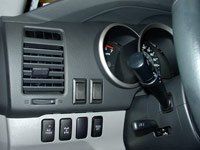
Rheostat relocation.
In the pics above, the switch on the left is for my Footwell lighting mod and the switch on the right is for the this Maplight modification.
Since the factory rheostat switch went in the cutout on the left you may be wondering what happened to it. I relocated it to the area inside the
fuse box located in the driver side lower finish panel. The factory wiring reaches there with no extension needed. I have never used the rheostat
(dash light dimmer switch) on this vehicle or any other vehicle for that matter. I have driven a few road trips thru the night (8 hours of darkness) and
never felt the need to dim the dashboard lights whatsoever. So relocating the switch to an inconvenient area to use was well worth the dash slot that was
freed up.
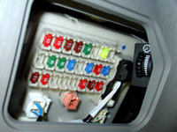
Rheostat relocated |
Pics.
In the pics below, you can see the improved lighting in the front seat and dash areas with the maplight modification in use.
All lighting in these two pics are shown with Led Interior replacement bulbs. These pics
were taken one right after the other with a consistent 1 second exposure with the camera mounted on a tripod.
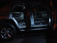
Before Maplight Mod |
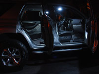
After Maplight Mod |
|
|