|
Main Menu
|
|
|
|
My 2007 4Runner
|
|
|
|
4Runner History
|
|
|
|
Other
|
|
|
|
|
Concept:
This modification will add the ability to activate the factory backup camera on demand, rather than in reverse only.
I built my anytime backup camera mod in combination with my Nav Video Mod.
Many people have inquired specifically about the anytime backup camera portion of the mod.
They indicated that they were interested in a simplier version of the full write-up that focused only on the anytime camera portion of the mod.
This webpage addresses that.
What needs to be accomplished:
The factory Toyota navigation setup has a backup camera system that when the vehicle is put into reverse, it automatically sends a video signal from the backup camera housed within the
rear tailgate, up to the nav screen.
A switch will be added to fool the navigation system into thinking the vehicle is in reverse even though we are not. This "anytime backup camera" switch will activate the camera and
automatically force the nav screen to change from whatever is currently being displayed on it (such as maps, audio, etc.), to a direct video feed from the camera.
Building the anytime backup camera module:
We need to build switch activated relay circuit that will allow the user to activate the backup camera on demand.
A dual throw relay is used to isolate the signal so that it does not back feed into the ecu which may cause some adverse issues.
Let's start with the basics and look at a normal automotive 12V single pole dual throw relay available at any automotive parts store.
single pole dual throw (SPDT) relay |
The relay can be in either the unenergized or energized states. Let's start with unenergized as seen here.
unenergized SPDT relay |
To start wiring this for the backup camera mod. Find the red with yellow stripe reverse camera wire behind the nav screen.
Cut it clear thru...in half. Wire the cut side coming from the vehicle to pin 87a on the relay and the cut side to the nav screen to pin 30.
By doing this you basically put the cut wire back together and your vehicle will function as normal.
But when the relay is energized (which occurs when one side of the coil has 12V+ and the other side 12V-) the red with yellow stripe wire is "opened" (disconnected). See figure 3.
energized SPDT relay |
To energize the coil you need to have positive and negative at pins 85 and 86. So simply run a ground to pin 86 first.
Then wire a single pole single throw switch so that 12V positive goes to one side of the switch and the other side goes to pin 85 on the relay.
When you turn the switch on the relay is energized and the reverse wire is "broken".
With the switch on and the reverse sensor wire is broken, we can send a 12V positive signal thru the relay (via pin #87) and out to the camera via pin 30 with out backfeeding it to the vehicle which is at pin 87a.
How do you get 12V+ to 87? Simple, just send a wire from the switch output to 87 as well as 85 at the same time.
The nav screen sees 12V positive coming in and turns on even while moving forward, but since the 12V positive is not feeding thru out the circuit to the vehicle no adverse effect are realized.
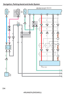
Here is the complete anytime backup camera mod, in schematic form, which also shows how it is wired into the factory Toyota 4Runner navigation system.
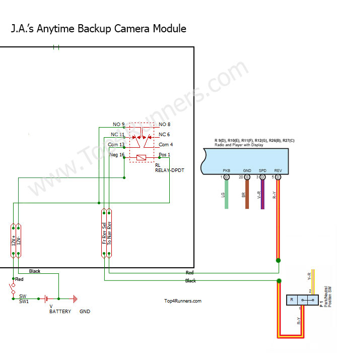
J.A.'s Anytime Backup Camera Schematic |
And here is the completed anytime backup camera portion of the full Nav Video Mod.
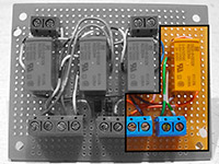
Anytime Backup Camera portion
of the full Nav Video Module |
Installing the anytime backup camera module:
Begin by remove navigation unit to access the wiring behind it.
Remove driver side lower finish panel.
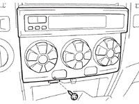
Start out by disassembling the lower dash area.
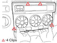
First remove the two 10mm bolts holding the lower finish panel on. Pull the panel straight out to disengage 4 plastic clips still holding it on.
The trim ring around the key hole will just pop out on it's own as you are doing this. Remove the wire harnesses attached to each of the switches
located on the back side of this panel. Also on the back right side of this lower finish panel is the room temperature sensor harness (cooler thermistor),
detach this from the panel as well. You may leave the fuel door release and the hood release handles attached to the panel. The panel can be lowered
to the floor now.
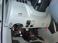
Remove driver side
lower finish panel |
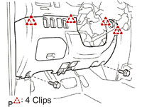
Pull to release 4 clips |
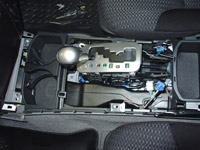
Center Console Removal.
To remove the center console, start by removing the shifter cover. It is held on with five clips and two claws. To remove you simply pull straight
up and back towards the rear of the vehicle. Before you can set the shift cover aside you need to remove any wire harnesses attached to it.
In my case I had to remove the DAC switch wiring and the 12v power point wiring. You may have more if you have the seat heaters,
rear air suspension or cigarette lighter options.
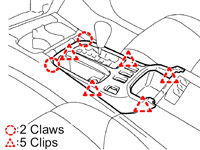
To remove shift cover
Pull to release 5 clips |
Next the console cover gets removed, this time there are 6 clips and two claws. To remove, again, pull straight up and back towards the rear of the
vehicle.
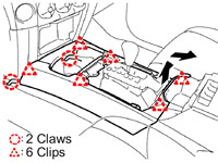
To remove console cover
Pull to release 6 clips |
Before you can lift out the center console itself, you need to remove the upper panel side garnish. To remove, unclip the side covers just in front of
and below the cupholders. Then slide rearward to remove.
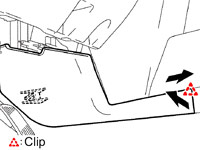
To remove side garnish
Pull to release 1 clip |
Then using a 10mm socket, remove the six bolts holding the console in place.
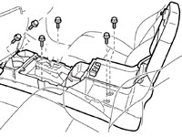
Remove six 10mm bolts |
Bolts removed |
Disconnect 4 more harnesses (automatic transmission shift lever illumination, accessory input for stereo, 115v power point and cup holder illumination),
then lift out entire console and set aside.
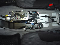
Lift out center console |
Set console aside |
Center Instrument Cluster Removal.
To remove the center instrument cluster, start out by opening the storage bin under the climate control assembly.
Using a 10mm socket, remove the one bolt that is in there.
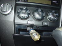
Using a 10mm socket |
Remove bolt |
Disengage the 4 clips and remove the air conditioner assembly, and then disconnect the wiring connector on the back.
Pull to release 4 clips |
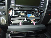
Pull forward and disconnect wire harness |
Climate control assembly removed |
Now you can remove the center instrument cluster finish panel sub-assembly. First remove 3 bolts using a 10mm socket.
Then disengage the 8 clips. At this point you can disconnect the three wire connectors from the hazard lights, rear window control and 4WD selector.
Set the panel aside.
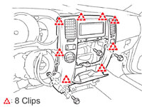
Remove 3 bolts
Pull to release 8 clips |
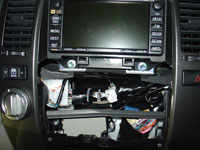
Using the 10mm socket, this time with and extension bar, remove 4 bolts holding in the navigation unit. Pull the navigation unit straight out. In order to work on the wiring, you will
need to disconnect the 9 wire harnesses on the back side. Then set the navigation unit aside.
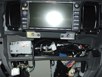
Center instrument cluster finish panel removed |
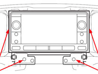
Remove 4 bolts
Pull navigation unit straight out |
Remove 4 bolts
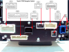
Navigation connectors |
Wire Connections:
With the navigation unit out of the dashboard, it is time to splice our module into the factory wiring.
Identify and cut in half the backup camera trigger wire which is the red wire with yellow stripe located at pin5 in the R9 connector.
Run a wire from the connector side of the cut wire to the common prong of the relay (pin 30 or 13).
Run the other side of the wire to the normally closed prong of the relay (pin 87a or 11).
Run a ground wire to one side of the relay coil (pin 86 or 16).
Run switched 12V+ to the other side of the relay coil (pin 85 or 1).
Also run switched 12V+ to the normally open prong of the relay (pin 87 or 9).
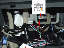
Backup camera trigger wire identified |
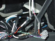
Splice made at reverse cam trigger wire
ready to heat shrink |
Install Switches:
A 12V spst switch is needed for this mod.
I used a round rocker switch with amber led that matches the one I used for my Navigation Override and Unlock Bypass Mod.
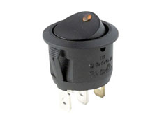
Round rocker switch
with amber led |
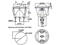
12V round rocker
switch info |
Switch information:
12V Round Rocker with Amber LED. Oznium.
Switch Type: Rocker Switch
Circuitry: Single Pole Single Throw (SPST)
Terminals: 3 standard male brass blades, 0.25" wide x 0.295" long (6.35mm x 7.5mm).
Up Position: On (2-1).
Down Position: Off.
Electrical Rating: 10 amps at 250V AC, 15 amps at 125V AC
Illuminated: Yes.
Housing: Black plastic bezel and actuator.
Mounting Panel snap-in.
Panel Thickness: fits panels 3mm max thickness.
Mounting Hole Dim. Inch 0.775" (19.8mm).
Bezel Size: 0.906" (23.0mm).
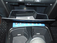
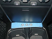
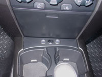
I decided to locate the switch that activate this mod on the blank panel right behind the cupholders. I found a nice 12V round rocker switch with amber led that only required
a simple 3/4" hole to be drilled for installation. This switch fits perfect and is low profile enough that it allows the bin under the radio to open fully without interfering
with the switch. I used 3/4" washers to layout the spacing and check for clearance before drilling.
I am using this panel to house multiple switches for various mods. So the pics that follow so me installing multiple switches all at once.
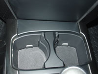
4Runner center console
cupholder area |
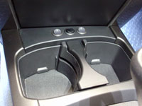
Laying out switch panel |
Checking for clearance |
Checking for clearance |
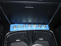
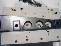
You will notice I'm installing three of these switches in total.
This panel will hold between five to seven switches depending upon the spacing used between them.
Drawing the drilling pattern |
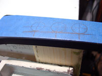
Preparing to drill |
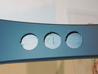
Holes for switches drilled
switch notches carved |
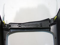
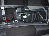
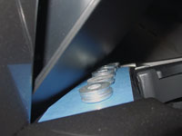
Underside of center console |
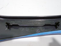
Panel support |
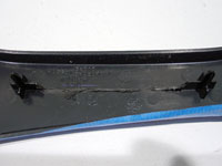
Panel support removed |
Support panel drilled |
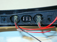
Switches mounted |
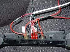
Switch panel wired up |
Round rocker switches |
Switches installed |
After completing the installation of the relay module, associated wiring and switch, reinstall the navigation system back into dash.
Results:
The Anytime Reverse Camera feature can be quite useful while towing and wanting to check on the hitch connection.
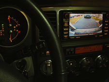
Anytime reverse camera
shown while in park |
|
|