|
Main Menu
|
|
|
|
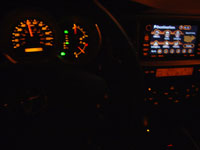
My 2007 4Runner
|
|
|
|
4Runner History
|
|
|
|
Other
|
|
|
|
|
Concept:
I special ordered my 2007 4Runner and chose to include the optional
Toyota DVD Navigation System. This was a $2,137 invoice ($2,620 retail) option which included a JBL® AM/FM 4-disc CD changer with voice-activated
DVD navigation system, satellite radio capability, hands-free phone capability via Bluetooth® wireless technology, backup camera,
eight speakers and MP3/WMA playback capability. It required options FE (50 State Emission Equipment, no charge) and
NJ (Homelink Garage Door Opener, $100/$125).
For that amount of money you get the privelage of having it's most useful features "locked out" while driving above 5mph.
To that end, I have built a Navigation override bypass module which unlocks the Toyota Factory Navigation system to allow for full usage of all
locked items (destination address input, points of interest, all navigation functions unblocked, phone number entry, audio playlists, etc.)
while the vehicle is in motion.
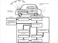
Navigation System Overview:
Through the use of the Global Positioning System (GPS) and map data which is stored on a DVD,
the navigation system analyzes the position of the vehicle and indicates the position on the map that is displayed on the screen.
Toyota (and Lexus) navigation systems use two methods to track the current vehicle position.
1) GPS (Global Positioning System) satellite navigation and 2) autonomous (dead reckoning) navigation.
Both navigation methods are used in conjunction with each other.
The GPS navigation method detects the absolute vehicle position using radio waves from GPS satellites.
GPS satellites were originally launched by the U.S. Department of Defence for military purposes. The GPS uses a minimum of 24 satellites in 6 orbits.
At any point in time, 4 satellites should be able to pinpoint your vehicle. However, GPS signals may not reach the vehicle due to
influence from the surroundings, vehicle direction, and time.
The combination of autonomous and GPS navigation makes it possible to display the vehicle position even when the vehicle is in places where the
GPS radio wave cannot receive a signal.
The autonomous navigation method determines the relative vehicle position based on the running track determined by vehicle speed sensors as well as
by gyro sensors located in the navigation assembly.
Navigation System Overview |
What needs to be accomplished:
Toyota has set the navigation system so that when the vehicle is traveling over 5 mph, features that they feel may distract the driver become locked out.
Those locked features unlock when the vehicle is stopped or is traveling under 5 mph.
At first thought, it seems as though a simple inline switch on the vehicle speed sensor wire going to the navigation system would unlock the
system and allow your passenger to utilize the nav system while the vehicle is moving. Initially this works, but when the GPS sensor senses movement
while there is no speed signal present, the system will again lockout all features after 15 seconds.
What needs to be accomplished is to trick the system into believing the vehicle is traveling under 5 mph, when in reality it can be traveling at any speed.
To do this we need to understand how the vehicle speed sensor works.
The 4th generation 4Runner has four ABS Speed Sensors, one at each wheel.
Each speed sensor generates four 5-12V pulses per wheel revolution and sends these signals to the Skid Control Electronic Control Unit (ECU).
The skid control ECU processes these signals and sends them along to the combination meter.
The combination meter conditions these signals into a more precise digital square waveform pulse signal via a transistor based waveform shaping circuit
inside the meter itself. The pulse signal is then transmitted to the navigation system which determines the vehicle speed based on the frequency of these
pulses.
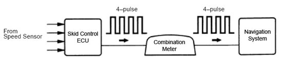
Pulse processing |
To trick the system into believing the vehicle is in motion but traveling at a speed under 5mph, we will use a switch to interrupt the speed sensor
signals coming from the combination meter and an electronic circuit to replace them with our own signals that replicate those in which would be generated
if the vehicle was moving at about 3mph. My navigation override and unlock bypass module will accomplish that.
Building the navigation override and unlock bypass module:
So we need to build an electronic circuit that oscillates between two states producing a square waveform with a frequency of 4 pulses per second (4htz).
A square wave is a digital waveform with sharp transitions between low state (0V) and high state (+5-12V).
Also, we need the duty cycle, the proportion of the complete cycle for which the output is high, to approximate 50%.
An Astable multivibrator electronic circuit will accomplish this.
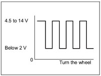
Square waveform at 4 hertz |
During the research and testing phase of this modification, I designed and worked out the kinks of this speed pulse generator circuit by testing it
using an electronic circuit simulator.
Clicking the link will open a pop up window with my circuit running on the simulator.
Here is that same pulse generator circuit, being used as a navigation override, in a schematic form I created showing how it is wired into the
factory Toyota 4Runner navigation system.
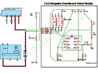
J.A.'s Navigation Override Module Schematic |
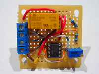
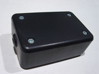
Here are some pics of the parts needed to build the navigation unlock module. I built it to fit in the smallest project box I could find at Radio Shack,
to make it easier to mount this behind the factory navigation unit. Some features that I included are;
a dual throw relay which allows me to use a single throw switch of my liking not available in dual throw configuration,
screw terminal block connectors make for easy on vehicle installation rather than direct soldered main connection wires,
bypass cap which helps filter the electrical noise out of the circuit by removing the alternating currents caused by ripple voltage,
gold plated low profile dip socket adapter,
high precision resistors and adjustable potentiometer to help with fine tuning the final frequency.
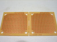
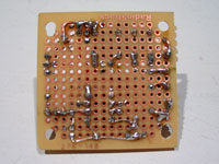
Dual Printed Circuit Board |
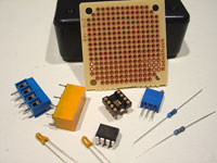
Parts |
Trimming inside of project box |
Test fit pc board |
I preset the potentiometer and tested all components before soldering.
100K trimming potentiometer
presetting to 47K |
130K resistor |
1K resistor |
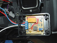
Here is the completed navgation bypass module and what it looks like fitted into the project box.
Completed Nav Override Module
Front |
Completed Nav Override Module
Back |
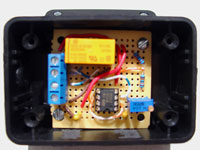
PCB mounted to Project Box |
Nav Override and Unlock
Bypass Module |
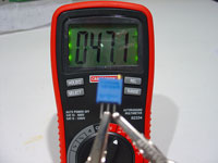
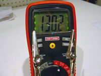
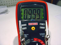
Before installation, I test the completed circuit on a digital multimeter and performed the final calibration.
I find that setting the unit to produce 4 pulses per second, or 4 hertz, simulates the vehicle traveling at 3mph.
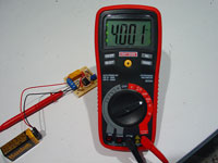
Measuring and calibrating Hertz |
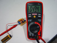
Measuring Duty Cycle |
Installing the navigation override and unlock bypass module:
Begin by remove navigation unit to access the wiring behind it.
Remove driver side lower finish panel.
Start out by disassembling the lower dash area.
First remove the two 10mm bolts holding the lower finish panel on. Pull the panel straight out to disengage 4 plastic clips still holding it on.
The trim ring around the key hole will just pop out on it's own as you are doing this. Remove the wire harnesses attached to each of the switches
located on the back side of this panel. Also on the back right side of this lower finish panel is the room temperature sensor harness (cooler thermistor),
detach this from the panel as well. You may leave the fuel door release and the hood release handles attached to the panel. The panel can be lowered
to the floor now.
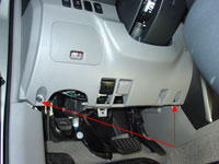
Remove driver side
lower finish panel |
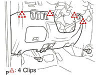
Pull to release 4 clips |
Center Console Removal.
To remove the center console, start by removing the shifter cover. It is held on with five clips and two claws. To remove you simply pull straight
up and back towards the rear of the vehicle. Before you can set the shift cover aside you need to remove any wire harnesses attached to it.
In my case I had to remove the DAC switch wiring and the 12v power point wiring. You may have more if you have the seat heaters,
rear air suspension or cigarette lighter options.
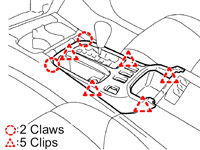
To remove shift cover
Pull to release 5 clips |
Next the console cover gets removed, this time there are 6 clips and two claws. To remove, again, pull straight up and back towards the rear of the
vehicle.
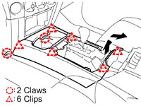
To remove console cover
Pull to release 6 clips |
Center Instrument Cluster Removal.
To remove the center instrument cluster, start out by opening the storage bin under the climate control assembly.
Using a 10mm socket, remove the one bolt that is in there.
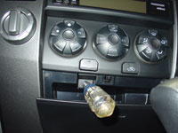
Using a 10mm socket |
Remove bolt |
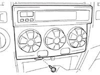
Disengage the 4 clips and remove the air conditioner assembly, and then disconnect the wiring connector on the back.
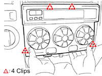
Pull to release 4 clips |
Pull forward and disconnect wire harness |
Climate control assembly removed |
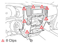
Now you can remove the center instrument cluster finish panel sub-assembly. First remove 3 bolts using a 10mm socket.
Then disengage the 8 clips. At this point you can disconnect the three wire connectors from the hazard lights, rear window control and 4WD selector.
Set the panel aside.
Remove 3 bolts
Pull to release 8 clips |
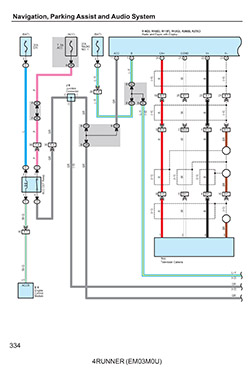
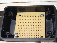
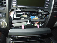
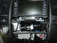
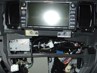
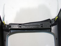
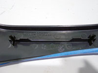
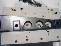
Using the 10mm socket, this time with and extension bar, remove 4 bolts holding in the navigation unit. Pull the navigation unit straight out. In order to work on the wiring, you will
need to disconnect the 9 wire harnesses on the back side. Then set the navigation unit aside.
Center instrument cluster finish panel removed |
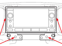
Remove 4 bolts
Pull navigation unit straight out |
Remove 4 bolts
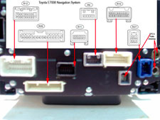
Navigation connectors |
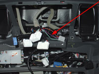
Find a location where you will place your navigation module hidden inside the dash.
Navigation module hidden inside the dash |
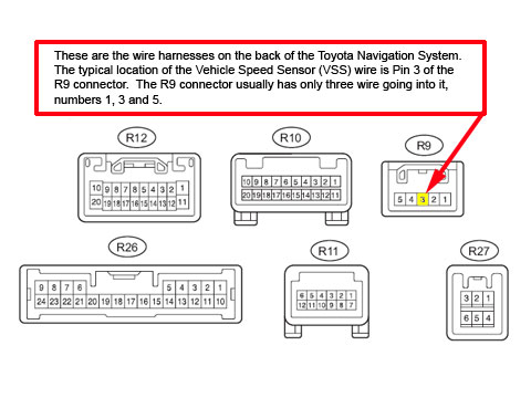
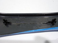
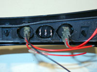
Locate the Vehicle Speed Sensor wire going into the rear of the navigation unit and cut it.
Refer to the picture below for the typical location of the VSS wire in the navigation wiring harness.
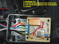
Get a legnth of wire (18 to 24 wire gauge is fine) long enough to reach between the vehicle speed sensor wire and the location in which you will keep the override module.
Splice this wire into the end of the speed sensor wire that is attached to the vehicle harness (not the one still attached to the connector).
Connect the other end of this wire to the override module, screw terminal #2.
Get another legnth of wire (18 to 24 wire gauge is fine) long enough to reach between the vehicle speed sensor wire and the location in which you will keep the override module.
Splice one end of this wire into the navigation connector side of the cut speed sensor wire.
Connect the other end of this wire to the override module, screw terminal #3.
Navigation wire connectors |
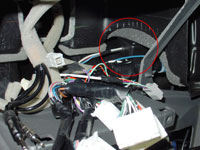
Navigation removed
vehicle speed sensor wire identified |
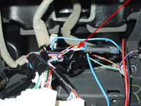
Splicing wires |
Simple 4 wire connection |
PCB mounted to Project Box |
Connect module to ground.
Connect one end of a wire to screw terminal #4 and the other end to any ground source on the vehicle.
Install Switch
Install a single pole single throw 12 volt switch somewhere on the dashboard or center console.
Wire one terminal of this switch to a 12v positive power source that only has power when the ignition is on.
Wire the other side to the override module, screw terminal #1.
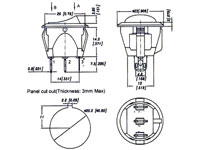
12V round rocker
switch info |
Switch information and installation:
12V Round Rocker with Amber LED
Switch Type: Rocker Switch
Circuitry: Single Pole Single Throw (SPST)
Terminals: 3 standard male brass blades, 0.25" wide x 0.295" long (6.35mm x 7.5mm).
Up Position: On (2-1).
Down Position: Off.
Electrical Rating: 10 amps at 250V AC, 15 amps at 125V AC
Illuminated: Yes.
Housing: Black plastic bezel and actuator.
Mounting Panel snap-in.
Panel Thickness: fits panels 3mm max thickness.
Mounting Hole Dim. Inch 0.775" (19.8mm).
Bezel Size: 0.906" (23.0mm).
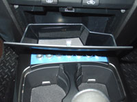
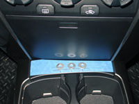
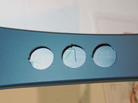
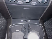
I decided to locate the switch that activates the navigation override on the blank panel right behind the cupholders. I found a nice 12V round rocker
switch with amber led that only required a simple 3/4" hole to be drilled for installation.
This switch fits perfect and is low profile enough that it allows the bin under the radio to open fully without interfering with the switch.
I used 3/4" washers to layout the spacing and check for clearance before drilling.
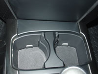
4Runner center console
cupholder area |
Laying out switch panel |
Checking for clearance |
Checking for clearance |
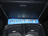
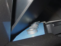
While I am at it, I'm installing three of these switches in total. Two will be used for upcoming mods in which I am in the planning stages right now.
This panel will hold between five to seven switches depending upon the spacing used between them.
Drawing the drilling pattern |
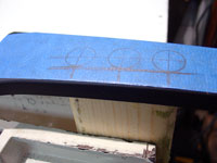
Preparing to drill |
Holes for switches drilled
switch notches carved |
Underside of center console |
Panel support |
Panel support removed |
Support panel drilled |
Switches mounted |
Round rocker switches |
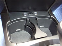
Switches installed |
After completion of the navigation unlock module, associated wiring and switch, reinstall the navigation system back into dash.
Testing the navigation override and unlock bypass module:
To check the override module is working correclty we can use the diagnostic check feature:
- After the ignition switch is turned ON, check that the map is displayed before starting the diagnostic mode.
- While pressing and holding the "INFO" switch, operate the parking light control switch: OFF | Turn ON | Turn OFF | Turn ON | Turn OFF | Turn ON | Turn OFF.
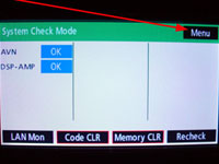
- The diagnostic mode starts and the "System Check Mode" screen will be displayed. Service inspection starts automatically and the result will be displayed.
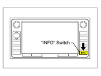
Info Button |
System Check Screen |
DIAGNOSIS MENU:
- The "Diagnosis Menu" screen will be displayed by pressing the menu switch on the "System Check Mode" screen as shown above.
- On the Navigation Check screen, press Vehicle Sensors.
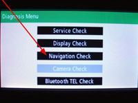
Diagnosis Menu |
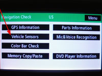
Navigation Check Menu |
With the override switch in the off position and the vehicle parked, review pulse count and speed information.
You will find the pulses and speed remain at zero.
Then turning the override switch on, you will notice that the pulse count rises in 4 pulse increments and the speed shows 3mph though the vehicle is stopped.
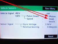
Pulse count
Override switch off
vehicle parked |
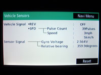
Pulse count
Override switch on
vehicle parked |
Pulse count rising |
EXITING DIAGNOSTIC MODE:
- Press and hold the "DISPLAY" switch for 3 seconds.
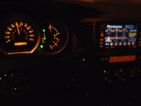
While driving, have your passenger turn the activation switch on. You will notice the previously dimmed (locked) features light up and are now
available for use. Please note that while the switch is activated, the navigation system may not track your position as accurately as usual.
This is because the override module is informing the navigation system you are traveling at 3mph. When the switch is turned back off the navigation
system will begin accurately tracking your location within a few seconds.
Before Override Module
features locked out |
After Override Module
features available while driving |
|
|