|
Main Menu
|
|
|
|
My 2007 4Runner
|
|
|
|
|
|
|
|
|
|
|
|
|
*New*
|
|
|
|
|
|
|
|
|
|
|
|
|
|
|
|
|
|
|
|
*New*
|
|
*New*
|
|
|
|
|
|
|
|
|
|
|
|
|
|
|
|
|
|
|
|
|
|
|
|
|
|
|
|
|
|
*New*
|
|
|
|
|
|
|
|
|
|
|
|
|
|
|
|
|
|
|
|
|
|
|
|
|
|
|
|
|
|
|
|
|
|
|
*New*
|
|
*New*
|
|
*New*
|
|
|
|
|
|
|
|
*New*
|
|
*New*
|
|
*New*
|
|
*New*
|
|
|
4Runner History
|
|
|
|
Other
|
|
|
|
|
Please note: if you have the 115V AC power outlet option and want to have full time power there as well,
go directly to the full time 115v power mod as it will simultaneously perform both the 115v and 12v power outlet mods.
Concept:
The 2007 Toyota 4Runner comes standard with one front and one cargo area 12V auxiliary power points.
Compare this to the 1999 4Runner which came standard with one front mounted 12V cigarette lighter,
two front and one cargo area auxiliary power points.
Both the auxiliary power points on the 4th gen 4Runner have power only when the ignition key is either in the
accessory or the on position. For various reasons a person may want to have power available at these points
when the vehicle is off. This modification accomplishes that.
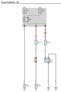
The power outlet relay (DC socket relay) is mounted in the driver side junction box located in the lower finish panel.
In the 3rd Gen it's mounted in the engine room relay box and literally is a 5 minute mod, for the 4th Gen allow a little more time.
Remove driver side lower finish panel for access to driver side interior relay/junction box.
Start out by disassembling the lower dash area as we need access to the driver side interior relay/junction box. To access this area,
first remove the two 10mm bolts holding the lower finish panel on. Pull the panel straight out to disengage 4 plastic clips still holding it on.
The trim ring around the key hole will just pop out on it's own as you are doing this. Remove the wire harnesses attached to each of the switches
located on the back side of this panel. Also on the back right side of this lower finish panel is the room temperature sensor harness (cooler thermistor),
detach this from the panel as well. You may leave the fuel door release and the hood release handles attached to the panel. The panel can be lowered
to the floor now.
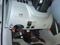
Remove driver side
lower finish panel |
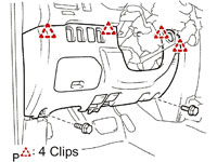
Pull to release 4 clips |
Remove lower bracket:
Remove two 10mm bolts holding the metal bracket around the bottom of the steering column. Disengage the 2 claws and remove the instrument panel lower
left hand bracket. Set bracket aside.
Remove instrument panel
lower bracket |
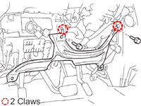
Disengage 2 claws |
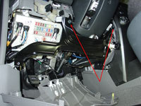
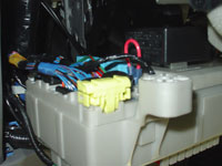
Lower down the driver side interior relay/junction box:
Remove wire clip and wire connector under steering column.
Remove three bolts holding driver side interior relay/junction box in place.
Remove bolt & bracket.
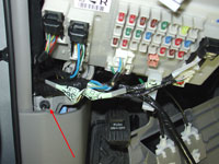
Pull down driver side interior relay/junction box to access back side.
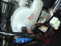
Remove wire clip
and wire connector under steering column |
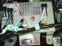
Remove three bolts |
Remove bolt & bracket |
Make a jumper wire by taking a 3 inch piece of 14 gauge wire and crimping on a .250" male solderless terminal to each end.
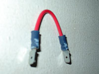
Jumper wire which will replace
the DC SKT Relay |
Remove the DC SKT Relay by pulling it straight out firmly.

Remove DC SKT Relay |
Insert one of the ends of the jumper we just made into the power outlet relay socket #3 and the other end
to socket #5. Sockets #3 and #5 are the only places a standard .250" male solderless terminal will fit,
so you won't have any trouble identifying where to insert the jumper wire. You will now have 12v power full time
to both the front and cargo area 12-volt auxiliary power points.
Jumper in place of DC SKT Relay |
Put everything back together. Now with the key off test that the power points have 12V power.
|
|